Wbs Work Breakdown Structure
. Certifications. Certification Types. Membership.
Volunteering. Learning & Events. Events. Thought Leadership.
Publications. Training & Development. PMI Job Board. PMBOK® Guide & Standards. About Standards.
Business Solutions. Store. About. Our Leadership & Governance.
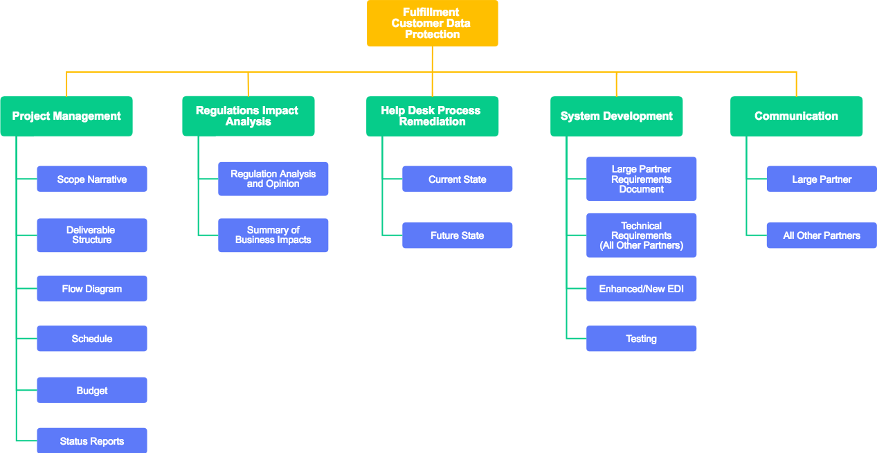
Jul 22, 2019 The work breakdown structure in project management visually defines manageable chunks of a project that a team can understand, as each part of the work breakdown structure gives further detail. The goal of WBS in project management is to make a large project manageable.
More. PMBOK® Guide & Standards. About Standards. Business Solutions.
Store. About. Our Leadership & Governance. IntroductionToday, project managers are more frequently finding high value in the creation of work breakdown structures (WBS) as they begin the process of project management. Exhibit 3-Centralized Tree StructureIt is clear that the WBS is the starting point in the planning process for many other essential project management processes such as estimating, scheduling and monitoring/controlling.
However, applying the WBS effectively to these processes remains a difficult task for many project managers. Exhibit 4-WBS to Project Schedule Transition Putting These Concepts to WorkTo illustrate how this process would be put into practice, a simple example will be used.
We will assume for this discussion that the WBS elements listed in the outline below are a few of the key scope components derived from an initial home building contract. Representing Levels 1, 2, 3, and 4, the high-level scope elements include the components of the primary structure, the foundation, exterior walls, roof, plumbing, electrical, and interior walls. The component element list (without hierarchical structure) appear to the project manager (from the contractor) as follows:.
House project. Primary structure. Foundation development. Layout—topography. Excavation. Concrete pour.
Exterior wall development. Roof development. Electrical infrastructure. Plumbing infrastructure.
Inside wall development: rough finishThe WBS in Hierarchical Outline FormTo organize this component list as it might be developed, the contractor might use the following hierarchical relationships (as even a novice might intuitively use). For this example, we will assume that this work is truly the correct representation. Working with the contractor, the project manager, then, would arrange the high-level deliverables for the house project in the following manner. Exhibit 5-House Project WBS Elements: An IllustrationHere, in Exhibit 5, Level 1 indicates that the work called “house project” represents 100% of the work of the project. All other scope (WBS) elements associated with the project would be subordinate to the house project element. At Level 2, there are four major components that make up the house project: primary structure, electrical infrastructure, plumbing infrastructure and inside wall development.
Level 3 shows the key components of the primary structure: foundation development, exterior wall development, and roof development. And finally the foundation development is decomposed into three work elements that become Level 4: layout-topography, excavation, and concrete pour.Granted, this is a highly simplified characterization of the work. It is used here, however, to help illustrate the WBS hierarchical concept, not necessarily the proper breakdown of all the work required to construct a home. Identifying Dependencies Between WBS ElementsLooking at this particular breakdown of the work, contractors, project managers, and homeowners alike would likely recognize that if this were the work to be completed, it would occur in a prescribed order, with some elements coming before—and being completed—before others begin. For example, it would be very helpful to build the foundation and walls before constructing the roof. Although it isn’t mandatory to do it in this way—building the foundation first and then the walls—establishing this order would allow the roof to be constructed on top of the walls, where it will ultimately be completed and integrated to secure the structure.
Certainly this is not the only approach to home construction, and the order can surely be modified to accelerate the building process, but for this illustration, we will presume a traditional home construction project, and the order would be: foundation, exterior walls, then roof.Once the foundation, walls, and roof are completed (and assuming additional details such as windows, doors, and exterior finish are part of the work), the construction can move to the interior of the home. Here, it would make sense to complete the electrical and plumbing work before putting the interior wall material in place. As before, this order is not mandatory, but common practice would indicate that the simplest, quickest, and easiest approach would be to first complete the work that would be hidden by the interior walls, then apply the interior wall material.
Again, for this example, we will use that convention. Representing Scope Sequence and DependencyWith the previous discussion in mind, a project manager could begin developing a very high-level representation of the work described by the scope (WBS) using nothing more sophisticated than pencil and paper to illustrate the dependencies described. Beginning with the house project element at Level 1, and including all of the WBS elements required to show the implied dependency, one representation of the work might look like the set of interrelated elements found in Exhibit 6. Exhibit 6-House Project High-Level Scope SequenceExhibit 6 shows how the project manager would use a sequence representation or an illustrated dependency map to indicate that foundation development (with its work packages, layout-topography, excavation, and concrete pour) must complete before the exterior wall development can begin, and that roof development depends on the completion of the exterior walls. Once the roof is complete, both the plumbing and electrical work can begin, but the interior walls would not start until the plumbing and electrical work are complete.
(In reality, the word “complete” here could mean “roughed-in,” where wires and pipes are run to and from their destinations but without fixtures attached to them.) It is important to note that the work elements shown here are not tasks or activities, but rather significant scope components that logically lead and follow one another. Once these elements (work packages) are decomposed via the process described earlier, the resulting tasks, activities, and milestones can be placed into the project scheduling tool. Taking the Process One Step Further: Introducing the Concepts of Inclusion and the Scope Relationship DiagramTo further ease the transition from the deliverable-oriented WBS to project schedule, we can refine the central process to illustrate more clearly the relationships between scope elements—before they are placed into the project schedule.In Exhibit 6 above, a scope sequence was used to show dependency between various WBS elements. In this illustration, each element is shown in linear fashion, using a two-dimensional sequential format, with lines connecting the elements to show predecessor and successor dependencies. To produce the network diagram, the two dimensions at the core of the process are order and precedence (or dependency). Although these two dimensions are critically important to the development of a network diagram, in some cases they are not sufficient to enable the project manager to easily envision the project schedule from the network diagram.Absent from this linear depiction of scope is the addition of a third dimension to complement order and dependency. To clarify: the concept/dimension of “inclusion” can be inserted into the process to convert the linear, two-dimensional network into a diagram that would depict how individual WBS elements are related to one another, as parent and subordinate elements, reflecting in graphic illustration, how they are developed and listed in an outline, chart, or WBS template.“Inclusion” as a dimension is used to show which elements are “part of” larger work elements, as well as to articulate clearly which WBS elements are not “part of” the work of others.
Stated another way, some work depicted by a WBS is intended to be seen as being “part of” a higher-order work element, whereas other elements in the WBS are clearly not “part of” specific higher-order elements.Using the example from the house project above, we will take another look at the hierarchical outline for the work. Describing this outline using the concept of “inclusion,” it is easy to see that the WBS elements 1.1, 1.2, 1.3, and 1.4—the primary structure, electrical infrastructure, plumbing infrastructure, and inside wall development are all “part of” the house project. They are integral to the completion of the project and are “included in” the work. By the same token, it is clear from the outline that the elements 1.1.1.1, 1.1.1.2, and 1.1.1.3 are all “part of” and “included in” the work that makes up the foundation development WBS element (1.1.1).Our sequence diagram in Exhibit 6 shows the precedence and dependency between these elements but does not clearly show which elements are actually “part of” the scope of other elements. In fact, if you examine Exhibit 6 carefully, you will notice that some of the elements have been left out of the diagram—for example, the Level 1 WBS element house project is not included.
Additionally, the first Level 2 element, foundation development is excluded, as are the three Level 4 elements, layout, excavation, and concrete pour. Why have they been excluded? Because including them in this drawing would be confusing and would disturb the illustration of the dependencies that are present. How would it be possible in Exhibit 6 to represent the Level 1 or Level 4 WBS elements without disturbing the logical flow of the dependencies between the relevant elements?
In truth, it is nearly impossible to properly include those elements in this illustration. To correct this issue and explain, we will examine the foundation development elements closely.In Exhibit 6 the foundation development elements at Level 4, layout-topography, excavation and concrete pour were excluded to reduce the confusion about the dependency between the Level 3 elements, foundation development (1.1.1), exterior wall development (1.1.2), and roof development (1.1.3). If we were to include them, however, they would also reflect their own natural or logical sequence. For instance, the layout of the foundation must precede any excavation—and the excavation must be complete before any concrete is poured. Considering the dependency between these elements, they could be shown as a series of scope elements executed in sequential fashion, under the “parent” element “foundation development” at Level 3. This concept is shown, as an excerpt from the house project, in Exhibit 8.
Exhibit 8-Foundation Development WBS Elements from the House ProjectIn this excerpt, it’s difficult to clearly envision or understand the relationship between the parent and children WBS elements other than that we have been told that the three elements at Level 4 are children of the parent element “foundation development”—which is not accurately represented in Exhibit 8. If we were to link the parent, the foundation development would appear as simply another node in the sequence, when in actuality it isn’t. In truth, the relationship between the foundation development element at Level 3 and its children at Level 4 is more clearly shown in the textual, outline form in Exhibit 9. Exhibit 9-Foundation Development Outline from House ProjectHere, it is easy to recognize the parent-child relationship between the Level 3 foundation development WBS element and the Level 4 elements, layout–topography, excavation, and concrete pour. Because of the indentation of the Level 4 WBS elements under the parent element, this outline form communicates to us and clearly shows that layout-topography, excavation, and concrete pour are actually “part of” and “included in” the work that is called foundation development.
Showing this in graphic format (see Exhibit 10) and using an alternative view to represent this parent-child relationship may help somewhat, but it does not fully capture the true relationship between the parent and child elements. Exhibit 10-Alternate Foundation Development Graphic from House ProjectIn Exhibit 10, it is difficult to determine the true relationship between the parent and child elements. Does “foundation development” come before or perhaps after the child elements? Of course, neither of those would be correct. Is foundation development above or below? Neither of those would be correct. Clearly, we need a better way to represent and communicate the relationship between these elements.To solve and illustrate how these relationships actually occur, a scope relationship diagram will be used instead to clearly show the relationships detailed in Exhibit 9, as well as the order and precedence shown in Exhibit 8.The resulting scope relationship diagram reflects the added dimension of inclusion representing these same WBS elements as follows in Exhibit 11.
Exhibit 11-Scope Relationship Diagram from House Project Foundation Development SegmentHere, in this scope relationship diagram representation, the foundation development WBS element, 1.1.1, is larger and visually includes the lower level elements 1.1.1.1, 1.1.1.2, and 1.1.1.3.With the addition of arrows to show the scope sequence described earlier, we are now able to illustrate how scope elements are planned within the concept of inclusion. In Exhibit 12 it is clear to see that the three elements at Level 4 are executed in sequence “within” or as “part of” the scope of the parent element, foundation development. Exhibit 13-Scope Relationship Diagram for House ProjectWith this illustration, demonstrating or describing which WBS elements are “part of” others is easy. The parent elements always include the child elements and appear as nested representations of work within the scope relationship diagram.
Moreover, it is easy to recognize which WBS elements are both parent and child. Nesting the scope elements clarifies the true relationship between the elements, a representation that previously could be illustrated only in outline form.To take this concept further, although the scope relationship diagram for the house project enables the visualization of the work “included” within the scope of each parent WBS element, it also allows a more direct and straightforward transition from deliverable-oriented WBS to project schedule. This results from the additional clarity that the scope relationship diagram provides, as it represents the relationships between WBS elements graphically, showing how they interact within the entire scope of the project.
Added benefits are also derived from this WBS representation. As decomposition is performed against the WBS elements in this scope relationship diagram (the lowest level being work packages), the resulting tasks, activities, and milestones can be easily grouped in the same manner as the WBS. These will be input to the project schedule and will facilitate the grouping of work that will be monitored and controlled during the execution of the project.Beyond the initial view in Exhibit 13, the various WBS elements can then be moved into a logical sequence. Dependency lines can be added to illustrate how the sequence of each of the scope elements within the project (parents and children) relate to and depend on one another. This reveals a logical representation of the sequence of the work to be performed. Using the scope relationship diagram from Exhibit 13, the logical sequence shown in Exhibit 14 would be produced by adding the dependency lines. Exhibit 14-Scope Relationship Diagram for House Project-with Scope SequenceUsing this approach, the project manager is able to use a step-wise process to create the linkage between the components of the deliverable-oriented WBS and the scope of the project, prior to further decomposition and development of the Project Schedule.
Most importantly, representing the WBS in this way may simplify the transition from WBS to a Project Schedule we described at the beginning of this concept discussion.To conclude this discussion, we want to be sure you are able to clearly see these two methods as reliable ways to transition from the deliverable-oriented WBS to the Project Schedule. So to recap, a clear path can be drawn from deliverable-oriented WBS to Project Schedule, if that path is taken through a logical sequence of decomposition and network diagramming. This concept is represented in Figure 15, which is a repeat of the concepts we discussed at the beginning of the discussion. Exhibit 15-WBS to Project Schedule TransitionAs we have described, once the WBS is complete, illustrated (documented) and placed under change management control, it becomes the foundation for other important aspects of the project, including the project schedule, risk management plan, budget and financial management plan, quality plan, resource management plan, and others. Beyond this, the WBS plays a vital role in the executing, monitoring, controlling, and closeout phases of a project, and in so doing, transitions from being seen primarily as a planning tool, to having an active role, where the WBS becomes the basis for decision making.
It establishes clear boundaries for the project during the initiating and planning phases, and provides a ready tool for ensuring those boundaries are protected during the remaining phases of the project. SummaryIn summary, applying the WBS to the project management life cycle is simply an outcome of effective scope analysis, WBS development, and careful project management execution, monitoring, and control by the project manager. Applying a carefully articulated WBS and WBS dictionary to subsequent project processes further utilizes tools such as the network diagramming technique or scope relationship diagram development and results in the creation of a baselined project schedule, drawn from the decomposition of work packages—which reveals key project tasks, activities, and milestones.
Berg, Cindy and Colenso, Kim. 2000, Work Breakdown Structure Practice Standard Project – WBS vs. Activities, PMI Network, April. 69.Chapman, J.
(2004, November) Work Breakdown Structures, Version 2.01. Retrieved 2/22/05, WebsiteHalli, Wayne. Scope Management through a WBS. Key to success for the Logan Expansion project. 12.Homer, John L and Gunn, Paul D.
Work Structuring for Effective Project Management. Project Management Institute 26th Annual Seminar/Symposium. New Orleans LA, October, 1995, p. 84.Kerzner H. Project management: A systems approach to planning, scheduling, and controlling (6th ed.). New York: John Wiley & SonsPMI (2004) A Guide to the Project Management Body of Knowledge (PMBOK ® Guide). Newtown Square, Pennsylvania: Project Management Institute Inc.PMI (2006) Practice Standard for Work Breakdown Structures – Second Edition.
Newtown Square, Pennsylvania: Project Management Institute Inc.Pritchard, Carl (1998), How to build a work Breakdown Structure, The cornerstone of Project Management. Arlington, Virginia: ESI InternationalRational Unified Process, Rational Software Corporation (1987-2001), Rational Unified Process, Overview, Retrieved 3/20/2005, Website:Haugan, Gregory T. (2002), Effective Work Breakdown Structures, Vienna, Virginia: Management Concepts,Macdonald Bradley, Inc (2002, December) Independent Verification and Validation White Paper (December 2002)., retrieved 2/20/2005, Website:U.S Department of Energy (2001, August) Performance Based Contracting: Development of a Work, retrieved 1/18/2005, Website.
A work-breakdown structure (WBS)[2] in project management and systems engineering, is a deliverable-oriented breakdown of a project into smaller components. A work breakdown structure is a key project deliverable that organizes the team's work into manageable sections. The Project Management Body of Knowledge (PMBOK 5) defines the work-breakdown structure 'A hierarchical decomposition of the total scope of work to be carried out by the project team to accomplish the project objectives and create the required deliverables.'
A work-breakdown structure element may be a product, data, service, or any combination thereof. A WBS also provides the necessary framework for detailed cost estimating and control along with providing guidance for schedule development and control.[3]
Overview[edit]
WBS is a hierarchical and incremental decomposition of the project into phases, deliverables and work packages. It is a tree structure, which shows a subdivision of effort required to achieve an objective; for example a program, project, and contract.[4] In a project or contract, the WBS is developed by starting with the end objective and successively subdividing it into manageable components in terms of size, duration, and responsibility (e.g., systems, subsystems, components, tasks, subtasks, and work packages) which include all steps necessary to achieve the objective.
The work breakdown structure provides a common framework for the natural development of the overall planning and control of a contract and is the basis for dividing work into definable increments from which the statement of work can be developed and technical, schedule, cost, and labor hour reporting can be established.[4]
A work breakdown structure permits summing of subordinate costs for tasks, materials, etc., into their successively higher level 'parent' tasks, materials, etc. For each element of the work breakdown structure, a description of the task to be performed is generated.[5] This technique (sometimes called a system breakdown structure[6]) is used to define and organize the total scope of a project.
The WBS is organized around the primary products of the project (or planned outcomes) instead of the work needed to produce the products (planned actions). Since the planned outcomes are the desired ends of the project, they form a relatively stable set of categories in which the costs of the planned actions needed to achieve them can be collected. A well-designed WBS makes it easy to assign each project activity to one and only one terminal element of the WBS. In addition to its function in cost accounting, the WBS also helps map requirements from one level of system specification to another, for example, a cross reference matrix mapping functional requirements to high level or low level design documents.The WBS may be displayed horizontally in outline form, or vertically as a tree structure (like an organization chart).
The development of the WBS normally occurs at the start of a project and precedes detailed project and task planning.
History[edit]
The concept of work breakdown structure developed with the Program Evaluation and Review Technique (PERT) by the United States Department of Defense (DoD). PERT was introduced by the U.S. Navy in 1957 to support the development of its Polaris missile program.[7] While the term 'work breakdown structure' was not used, this first implementation of PERT did organize the tasks into product-oriented categories.[8]
By June 1962, DoD, NASA and the aerospace industry published a document for the PERT/COST system which described the WBS approach.[9] This guide was endorsed by the Secretary of Defense for adoption by all services.[10] In 1968, the DoD issued 'Work Breakdown Structures for Defense Materiel Items' (MIL-STD-881), a military standard requiring the use of work breakdown structures across the DoD.[11]
The document has been revised several times, most recently in 2018. The current version of this document can be found in 'Work Breakdown Structures for Defense Material Items' (MIL-STD-881D).[12] It includes WBS definitions for specific defense materiel commodity systems, and addresses WBS elements that are common to all systems.
Defense Materiel Item categories from MIL-STD-881D are:
- Aircraft Systems
- Electronic/Generic Systems
- Missile/Ordnance Systems
- Strategic Missile Systems
- Sea Systems
- Space Systems
- Ground Vehicle Systems
- Unmanned Maritime Systems
- Launch Vehicle Systems
- Information Systems/Defense Business Systems
The common elements identified in MIL-STD-881D, Appendix K are: Integration, assembly, test, and checkout; Systems engineering; Program management; System test and evaluation; Data; Peculiar support equipment; Common support equipment; Operational/Site activation; Contractor Logistics Support; Industrial facilities; Initial spares and repair parts. The standard also includes additional common elements unique to Space Systems, Launch Vehicle Systems, and Strategic Missile Systems.
In 1987, the Project Management Institute (PMI) documented the expansion of these techniques across non-defense organizations. The Project Management Body of Knowledge (PMBOK) Guide provides an overview of the WBS concept, while the 'Practice Standard for Work Breakdown Structures' is comparable to the DoD standard, but is intended for more general application.[13]
Design principles[edit]
100% rule[edit]
An important design principle for work breakdown structures is called the 100% rule.[14] It has been defined as follows:
- The 100% rule states that the WBS includes 100% of the work defined by the project scope and captures all deliverables – internal, external, interim – in terms of the work to be completed, including project management. The 100% rule is one of the most important principles guiding the development, decomposition and evaluation of the WBS. The rule applies at all levels within the hierarchy: the sum of the work at the 'child' level must equal 100% of the work represented by the 'parent' and the WBS should not include any work that falls outside the actual scope of the project, that is, it cannot include more than 100% of the work… It is important to remember that the 100% rule also applies to the activity level. The work represented by the activities in each work package must add up to 100% of the work necessary to complete the work package.[15]
Mutually exclusive elements[edit]
Mutually exclusive: In addition to the 100% rule, it is important that there is no overlap in scope definition between different elements of a work breakdown structure. This ambiguity could result in duplicated work or miscommunications about responsibility and authority. Such overlap could also cause confusion regarding project cost accounting. If the WBS element names are ambiguous, a WBS dictionary can help clarify the distinctions between WBS elements. The WBS Dictionary describes each component of the WBS with milestones, deliverables, activities, scope, and sometimes dates, resources, costs, quality.
Plan outcomes, not actions[edit]
If the work breakdown structure designer attempts to capture any action-oriented details in the WBS, the designer will likely include either too many actions or too few actions. Too many actions will exceed 100% of the parent's scope and too few will fall short of 100% of the parent's scope. The best way to adhere to the 100% rule is to define WBS elements in terms of outcomes or results, not actions. This also ensures that the WBS is not overly prescriptive of methods, allowing for greater ingenuity and creative thinking on the part of the project participants. For new product development projects, the most common technique to ensure an outcome-oriented WBS is to use a product breakdown structure. Feature-driven software projects may use a similar technique which is to employ a feature breakdown structure. When a project provides professional services, a common technique is to capture all planned deliverables to create a deliverable-oriented WBS.[16] Work breakdown structures that subdivide work by project phases (e.g. preliminary design phase, critical design phase) must ensure that phases are clearly separated by a deliverable also used in defining entry and exit criteria (e.g. an approved preliminary or critical design review).
Level of detail[edit]
One must decide when to stop dividing work into smaller elements. For most projects a hierarchy of two to four levels will suffice. [17] This will assist in determining the duration of activities necessary to produce a deliverable defined by the WBS. There are several heuristics or 'rules of thumb' used when determining the appropriate duration of an activity or group of activities necessary to produce a specific deliverable defined by the WBS.
- The first is the '80 hour rule' which means that no single activity or group of activities at the lowest level of detail of the WBS to produce a single deliverable should be more than 80 hours of effort.
- The second rule of thumb is that no activity or group of activities at the lowest level of detail of the WBS should be longer than a single reporting period. Thus if the project team is reporting progress monthly, then no single activity or series of activities should be longer than one month long.
- The last heuristic is the 'if it makes sense' rule. Applying this rule of thumb, one can apply 'common sense' when creating the duration of a single activity or group of activities necessary to produce a deliverable defined by the WBS.
A work package at the activity level is a task that:
- can be realistically and confidently estimated;
- makes no sense practically to break down any further;
- can be completed in accordance with one of the heuristics defined above;
- produces a deliverable which is measurable; and
- forms a unique package of work which can be outsourced or contracted out.
Coding scheme[edit]
It is common for work breakdown structure elements to be numbered sequentially to reveal the hierarchical structure. The purpose for the numbering is to provide a consistent approach to identifying and managing the WBS across like systems regardless of vendor or service.[18] For example, 1.1.2 Propulsion (in the example below) identifies this item as a Level 3 WBS element, since there are three numbers separated by a decimal point. A coding scheme also helps WBS elements to be recognized in any written context and allows for mapping to the WBS Dictionary.[19]
A practical example of the WBS coding scheme is[20]
Elmedia player serial number for mac. Trust me that You will see a fantastic HD experience, smooth and even, no tearing or jerking of the video.The following one is Cracked then Re-packed. This one absolutely works in full functions without keygen, patch and serial number.I personally love all softwares designed by Elmedia for Mac, and is one of my common using App.With Elmedia Video Player you can play almost all file types: MP4, AVI, FLV, WMV, MKV, MP3, and more. This cool app does not need codecs to install and additional plugins.
1.0 Aircraft System
- 1.1 Air Vehicle
- 1.1.1 Airframe
- 1.1.1.1 Airframe Integration, Assembly, Test and Checkout
- 1.1.1.2 Fuselage
- 1.1.1.3 Wing
- 1.1.1.4 Empennage
- 1.1.1.5 Nacelle
- 1.1.1.6 Other Airframe Components 1.n (Specify)
- 1.1.2 Propulsion
- 1.1.3 Vehicle Subsystems
- 1.1.4 Avionics
- 1.1.1 Airframe
- 1.2 System Engineering
- 1.3 Program Management
- 1.4 System Test and Evaluation
- 1.5 Training
- 1.6 Data
- 1.7 Peculiar Support Equipment
- 1.8 Common Support Equipment
- 1.9 Operational/Site Activation
- 1.10 Industrial Facilities
- 1.11 Initial Spares and Repair Parts
Terminal element[edit]
The lowest element in a tree structure, a terminal element is one that is not further subdivided. In a Work Breakdown Structure such elements (activity or deliverable), also known as work packages, are the items that are estimated in terms of resource requirements, budget and duration; linked by dependencies; and scheduled. At the juncture of the WBS element and organization unit, control accounts and work packages are established and performance is planned, measured, recorded and controlled.[21] A WBS can be expressed down to any level of interest. Three levels are the minimum recommended, with additional levels for and only for items of high cost or high risk,[22] and two levels of detail at cases such as systems engineering or program management,[23] with the standard showing examples of WBS with varying depth such as software development at points going to 5 levels[24] or fire-control system to 7 levels.[25]
Consistent to norms[edit]
The higher WBS structure should be consistent to whatever norms or template mandates exist within the organization or domain. For example, shipbuilding for the U.S. Navy must respect that the nautical terms and their hierarchy structure put into MIL-STD[26] are embedded in Naval Architecture[27] and that matching Navy offices and procedures have been built to match this naval architecture structure, so any significant change of WBS element numbering or naming in the hierarchy would be unacceptable.
Example[edit]
The figure on the left shows a work breakdown structure construction technique that demonstrates the 100% rule and the 'progressive elaboration' technique. At WBS Level 1 it shows 100 units of work as the total scope of a project to design and build a custom bicycle. At WBS Level 2, the 100 units are divided into seven elements. The number of units allocated to each element of work can be based on effort or cost; it is not an estimate of task duration.
The three largest elements of WBS Level 2 are further subdivided at Level 3. The two largest elements at Level 3 each represent only 17% of the total scope of the project. These larger elements could be further subdivided using the progressive elaboration technique described above.
WBS design can be supported by software (e.g. a spreadsheet) to allow automatic rolling up of point values. Estimates of effort or cost can be developed through discussions among project team members. This collaborative technique builds greater insight into scope definitions, underlying assumptions, and consensus regarding the level of granularity required to manage the projects.
See also[edit]
References[edit]
- ^Systems Engineering Fundamentals.Archived 2006-02-11 at the Wayback Machine Defense Acquisition University Press, 2001
- ^'Glossary of Defense Acquisition Acronyms and Terms: Contract Work Breakdown Structure (CWBS)'. Defense Acquisition University. Retrieved 19 September 2017.
- ^Booz, Allen & Hamilton Earned Value Management Tutorial Module 2: Work Breakdown Structure, Office of Science, Tools & Resources for Project Management, science.energy.gov. Accessed 27. Dec 2011.
- ^ abcNASA (2001). NASA NPR 9501.2D. May 23, 2001.
- ^Electronic Industries Alliance Standard Systems Engineering Capability Model EIA-731.1
- ^Institute of Electrical and Electronics Engineers Standard for Application and Management of the Systems Engineering Process IEEE Std 1220-2005
- ^Fleming, Quentin W., Joel M. Koppelman 'Earned Value Project Management' CROSSTALK: The Journal of Defense Software Engineering July 1998, p 20
- ^Haugan, Gregory T., Effective Work Breakdown Structures, pp7-8
- ^DOD and NASA Guide, PERT/COST System Design, June 1962
- ^Hamilton, R. L., Study of Methods for Evaluation of the PERT/Cost Management System, MITRE Corporation, June 1964
- ^MIL-STD-881, 1 November 1968
- ^MIL-STD-881D, Work Breakdown Structures for Defense Materiel Items, 9 April 2018
- ^Haugan, Gregory T., The Work Breakdown Structure in Government Contracting, Management Concepts, 2003 ISBN978-1567261202
- ^Effective Work Breakdown Structures By Gregory T. Haugan, Published by Management Concepts, 2001, ISBN1567261353, p.17
- ^Practice Standard for Work Breakdown Structures (Second Edition), published by the Project Management Institute, ISBN1933890134, page 8
- ^Swiderski, Mark A., PMP workbreakdownstructure.com, PMBOK-Work Breakdown Structures. Accessed 16. June 2013.
- ^Levy, Lacie monday.com, Your Quick Start Guide to Work Breakdown Structure. Accessed 21. November 2019.
- ^MIL-STD-881C, Work Breakdown Structures for Defense Materiel Items, 3 October 2011, ¶4.3
- ^Ashe, Kenneth, Work Breakdown Structure, Accessed 23. May 2016.
- ^MIL-STD-881C, Work Breakdown Structures for Defense Materiel Items, 3 October 2011 Appendix A, ¶A.3
- ^MIL-STD-881C, Work Breakdown Structures for Defense Materiel Items, 3 October 2011, ¶3.1.4
- ^MIL-STD-881C, Work Breakdown Structures for Defense Materiel Items, 3 October 2011, ¶1.4.1
- ^MIL-STD-881C, Work Breakdown Structures for Defense Materiel Items, 3 October 2011, ¶2.2.4.2
- ^MIL-STD-881C, Work Breakdown Structures for Defense Materiel Items, 3 October 2011, ¶Fig.3-6
- ^MIL-STD-881C, Work Breakdown Structures for Defense Materiel Items, 3 October 2011, ¶Fig.3-1
- ^MIL-STD-881C, Work Breakdown Structures for Defense Materiel Items, 3 October 2011, ¶Appendix E
- ^Gilmer, Thomas (1982-08-04). Introduction to Naval Architecture. pp. pg98. ISBN9780870213182.
Further reading[edit]
- Pritchard, Carl L. Nuts and Bolts Series 1: How to Build a Work Breakdown Structure. ISBN1-890367-12-5.
- Project Management Institute Practice Standard for Work Breakdown Structures, Second Edition. Project Management Institute. 2006. ISBN1-933890-13-4. (Note: The Second Edition is an extensive re-write of the Practice Standard.)
- Haugan, Gregory T. Effective Work Breakdown Structures (The Project Management Essential Library Series). ISBN1-56726-135-3.
- Miller, Dennis P. Building Your Project Work Breakdown Structure -- Visualizing Your Objectives, Deliverables, Activities and Schedule'. ISBN1-42006969-1. (Note: This new book is essentially a facilitator's guide for planning a project based on the WBS.)
External links[edit]
- Media related to Work breakdown structures at Wikimedia Commons